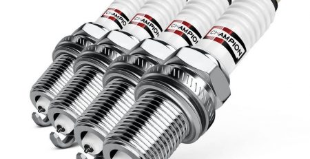
Anything and Everything You Want to Know About Spark Plugs
1991 SUPERFLOW ENGINE TECHNOLOGY CONFERENCE
WRITTEN BY: Dan VanderLey / Motorsports Engineer, Champion Spark Plug Co.
Mark Twain quotation – “Thunder is impressive and thunder is great but it’s lightning
that does the work.”
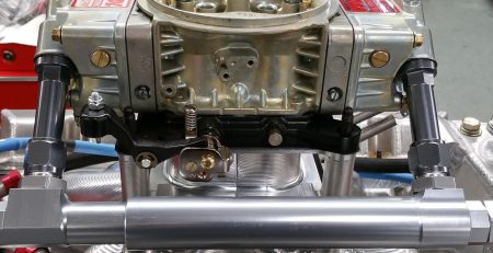
Definition – A device which provides a gap in the combustion chamber of an internal combustion engine across which an electrical discharge may occur which initiates the combustion of an air/fuel mixture.The spark plug performs a simple function in a complex environment. CANDLE IN A HIGH WIND just as in the title the candle is affected by the wind’s characteristics, so in our choice of plugs we must consider not only it’s basic function but more importantly the “wind” it operates in.
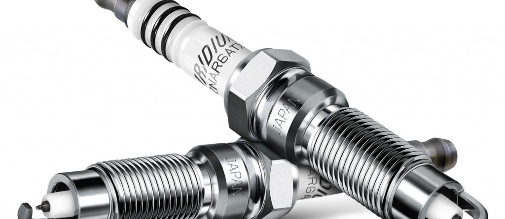
1. PARTS AND ASSEMBLY
A basic understanding of the parts and assembly will later help in the application and interpretation of the plug. (Cut-away plug below)
PARTS
A. Insulator – Aluminum oxide ceramic, must have good dielectric and mechanical strength, good thermal conductivity and resistive to heat shock
B. Center Wire – Must have good conductivity and be chemically and electrically erosion resistant (Approx. melt temp. of std nickel is 2500 degrees Fahrenheit)
C. Terminal Stud – Either solid post or removable terminal nut made from mild steel
D. Shell – Extruded or bar stock machined mild steel
E. Ground Wire – Typically made of same material as center wire
F. Washers (internal) material – Copper and steel
ASSEMBLY
A. Insulator – Molded dry under high pressure then kiln fired to vitrification at a temp. above the melting point of steel
B. Center Wire – Two pieces welded together, lower std. chrome nickel, upper iron (for strength in sealing process.) Center wire is dropped into the insulator then packed with sillment powder by a tamping process
C. Terminal Stud – The terminal stud has the cement applied then screwed on and tightened to a specific torque then allowed to dry or bake, providing a gas tight seal
D. Shell – After machining or extrusion the threads are rolled, then the ground wire is welded on and the unit is zinc or nickel-plated
F. Washer Material – Racing plugs then get washers and the insulator unit is placed inside the shell, sillment is added with tamping if the shell is cold pressed or if it is to be hot locked no sillment is added (c types are hot locked; s and v types are cold pressed) finally the ground wire is trimmed and the gap is set
***NOTE: While our racing plugs all have a positive contact between the center wire and the terminal stud, (because of a slight indentation in the terminal stud), not all plugs will show continuity when tested with an ohm meter. This is not a problem as the approx. .002″ gap which the low voltage (approx. 1.5V) ohm meter cannot bridge, causes effectively no resistance to the minimum 5000V of an ignition system. Some plugs have actually had a built in gap to combat a weak ignition/fouling problem.
2. Rating and Testing
A. Rating
Rating is referred to as “heat range”
Heat range is the plug’s thermal characteristics or its ability to transfer combustion heat from its firing end to the cylinder head.
Most heat is dissipated through the threaded and seating portion of the shell
Heat is transferred down the insulator nose to the seating or contact point of the insulator and shell, then out of the shell to the cylinder head.
A longer insulator nose = a hotter plug temp.
The insulator tip is the hottest part of the plug and therefore the part that could cause pre-ignition. For a typical 4-cycle engine this takes place at approx. 1750 degrees Fahrenheit
The rating of a plug’s heat range or its pre-ignition rating is done by an IMEP test.
B. Testing
1. IMEP TEST- SAE standard test # J551, single cylinder, constant comp. ratio, constant spark advance, and full throttle
IMEP rating is established by that power setting just below (1″ baro.) the point where the plug reaches pre-ignition as determined by a temp. sensitive indicator. There is a dramatic increase in cylinder temp. within the first few cycles under pre- ignition/detonation conditions. Higher IMEP numbers (psi) = colder plug. IMEP numbers are only good for comparison of the plugs ability to dissipate heat, not good for choosing a plug based on IMEP or BMEP of actual engine. Even though the SAE IMEP test is actually a load test the test engine design is so different and frictional losses are added back into the equation rendering the final figure useless for actual race engine IMEP or BMEP comparisons.
ex. BMEP = 150.8 X Torque/cubic in.
so for a V-8 310 CI engine with 420 ft.lb. of torque
BMEP = 150.8 X 420/310 = 204.3 psi
IMEP rating for a C57C = 450+
C63C = 370
RV15YC = 200
2. THERMOCOUPLE TESTING – used for establishing baseline temp. curve to determine most effective plug .
ex. idle temps – to determine anti-fouling needs
WOT temps – to determine maximum temps
Any change in the engine design i.e., type of cylinder head, cam, cam timing, comp. ratio, will change the temp. of the cylinder and therefore testing could be done.
Thermocouples are made in all common thread sizes and heat ranges
A thermocouple plug has a small temp sensitive element (a fused junction of platinum and platinum/10% rhodium) on the end of the insulator tip, being temp. sensitive the voltage at the junction increases as temp. increases and can be correlated to show exact temp. of plug at T.C. position.
3. FLAME ANALYZER or PRE-IGNITION TEST – basically a power source supplying a constant 10V to the spark plug with an oscilloscope showing the voltage curve indicated by the current flowing through the ionization of the plug gap.
From this curve we can determine:
1.burn rate of fuel mixture
2. auto-ignition – this is determined by intermittently removing the electrical charge from the ignition system to the spark plug and observing an ignition of the fuel at some point after the preset ignition time.
3. pre-ignition – when auto-ignition crosses to before set ignition timing. This test indicates how close to pre-ignition a plug is, allowing as hot a plug as possible to be chosen.
4. plug fouling – the baseline current flow increases as the plug becomes more fouled
4.ELECTRODE EROSION TEST or ENDURANCE TEST – subjecting the electrodes to a highly corrosive environment within the combustion chamber i.e., different fuels, lubricants, cylinder temps., ignition current, etc., to develop a product that will last
3. FACTORS AFFECTING PLUG PERFORMANCE
1. FACTORS AFFECTING THE TEMP. OF THE PLUG
Engine speed and load – as you increase RPM and load on an engine the temp. of the plug increases
Ignition Timing – great effect on plug temp., even after power curve has dropped off, increasing the timing with the engine under a load will result in a hotter plug temp.
Horsepower/Torque Increase – most changes that increases the power will result in an increase in plug temp. (ex. increasing comp.)
Cylinder Head Temp. – insulator tip temps. vary almost directly with cylinder head temp. When changing cylinder heads the cooling capability around the spark plug should be considered. Some later design heads have no water jacket around the plug hole.
Denotation – causes extreme and rapid rise in plug temp. which can then lead to pre-ignition and plug damage.
2. FACTORS AFFECTING THE VOLTAGE REQUIREMENT OF THE PLUG
Gap Spacing – With increases in gap comes an increase in “start up” voltage, but the “lock in” voltage remains relatively the same regardless of gap. Ex. fluorescent light – a 1′ long bulb or a 6′ long bulb use a very similar amount of voltage to keep the gases ionized but the larger bulb requires a substantially larger voltage (ballast/transfmr) to initiate the ionization.
Electrode Temp. – as the insulator temp. and electrode decreases the voltage required to create a spark increases. This is not so critical at higher RPM where the plug temp. is relatively high regardless of the plugs heat range, but it could be critical on a cold plug/low RPM situation where a weak spark could promote fouling. Note * lower power race engines require as much ignition as their higher power cousins because though igniting the mixture may be easier due to lower compression it’s made more difficult because of the lower cylinder temp. and too good a fuel quality.
Fuels – fuel conductivity will affect the voltage requirement in that a very conductive fuel can, when it wets the spark plug, bleed off a portion of the electrical charge. A good example is methanol which is a very conductive and requires and very strong ignition system.
3. FACTORS AFFECTING THE EFFICIENCY OF THE PLUG
Plug Location – most important factor concerning the plug next to the heat range. The first 10% of flame burn greatly affects the remaining 90%, i.e. if the flame burn begins very slowly the remaining comb. process will take place at a slow rate, therefore the manner in which the flame front is initiated is very critical to the engine’s performance. With that said it is obvious that the plug should be unshrouded to promote a larger initial flame kernel.
Some theories on plug location:
1. Plug should be centrally located in the combustion chamber so the flame can spread omni-directionally resulting in a faster burn rate. Minimal length of flame travel = faster burn rate = quicker pres. rise = less denotation tendencies
2. Plug should be located near the exhaust valve – having a hot exhaust valve located near the end gases promotes denotation, therefore locating the plug near the exhaust valve places the end gases in a cooler environment resulting in a decrease in denotation, this plug location also promotes rapid combustion because the heat from the exhaust valve promotes the 10% burn rate resulting in less ignition timing needed with a more rapid pressure rise.
3. Plug location relative to the swirl within the combustion chamber – there are two schools of thoughts on this:
A) Consider a turbulent mixture of vortices, if the spark occurs at the center of a vortex (a), the flame must spread without the aid of turbulence until it reaches the vortex boundary, on the other hand, ignition at the vortex boundary (b), will immediately aid the spread of flame because of the shearing action encountered.
B) A plug located on the vortex boundary can become so beaded with fuel wet fouling can occur (most common at lower RPM) ex. restart hesitations experienced by methanol fueled sprint cars
Multiple spark plugs – can reduce cyclic variation in the 10% fuel burn at lower RPM because there is a better opportunity for the ignition point to be in a proper air/fuel mixture and be near a vortex edge to propagate the flame. Also used in applications where large amounts of fuel are making it difficult to ignite the mixture, in this case 2 plugs are used with 2 separate ignition systems to create enough heat (current density) to reduce misfires. Can also reduce denotation because of reduced combustion time, provided the spark is retarded enough to hold peak pressure at optimum value. The negative side to this arrangement is that the multiple flame fronts create a lean spot where they meet thus creating less power and potentially harming the engine. In an ideal engine a multiple plug arrangement would show no benefit over a centrally located single plug but there is no ideal engine.
4. PLUG TYPES – FACTS AND FICTION
Resistor/ Suppressor – its function is to control electromagnetic interference. In a racing engine with a capacitive discharge ignition it will slightly lower the energy delivered at the plug gap. A possible benefit may be that with so much electronics being used in today’s racing, (engine management systems, date acquisition systems, etc.), the reduction of the electromagnetic interference may be very important. However with high output ignitions the resistor may burn out.
Gap Styles:
1. Standard Gap or J-gap – places spark plug approx. 1/16″ in the combustion chamber. Can be used with the ground wire in the Full coverage, Half coverage, or Corner gap configuration. Less gap wire coverage tends to give better spark exposure, because the arc is not behind so much of the ground wire. The arc tends to take place at the point of least resistance which typically is the shortest distance between to points. That is normally on the back side of the center wire because of the turn down of the ground wire going towards the shell. Also in the cold heat range plugs the ground wire becomes the hottest point in the combustion chamber and thereby the limiting heat range factor so shortening the ground wire may add a bit of insurance by reducing this hot spot.
2. Projected Core Nose – places the spark an additional 1/8″ into the combustion chamber. Originally designed to prevent fouling by exposing the insulator/ center wire to the air fuel path and heat of the cylinder. In street applications it performs as a hotter plug at lower RPM while running cooler at higher RPM. This is due to the cooling effect of the fuel charge on the projected tip. In racing it does the same thing, however it has limitations because the core nose length and the long ground wire limit the ability to build the colder heat ranges in this configuration. If this plug could be built in a colder heat range it would be ideal for super-speedway use, but as it is its use is normally limited to short tracks, some road courses, and sometimes qualifying on the big tracks. Because it physically moves the ignition point it can more centrally locate the ignition which reduces combustion time. It can also place the ignition point in a more efficient location based on swirl. In some cases this plug has the same effect as increasing ignition timing.
3. Retracted Gap – designed for high out-put engines where plugs could not be built cold enough with regular style ground wires. For use in F-1 and Indy style engines with very high cylinder pressures and temps. and ground wire clearance problems. Some of these plugs have silver center wires to further help dissipate the heat. This type of plug should only be used when absolutely necessary as it provides the least amount of combustion incentive of all the plugs.
4. Surface Gap – originally designed for outboard 2-stroke engines which had a bad fouling problem from dirty fuel causing major deposits on the insulator which in turn caused pre-ignition/denotation. These plugs are so cold they have no measurable heat range, they also require a very high energy CD ignition system. We have recently added a “surface air gap” plug which does have some insulator nose length giving it a measurable heat range. These plugs are very popular in the current F-1 engines. With the fine center wire. (.052″), and somewhat exposed core nose this plug works very well with high energy ignitions.
5. U-Groove Ground wire – the only possible advantage to this plug would be a more exposed spark due to the fact that there is no center of ground wire to fire to. The same thing can be accomplished with a fine ground wire/corner gap design. Nelson Crozier had a conversation with one of the engineers from Nippendenzo who was involved with the development of this plug and he relayed that the reason for the U-shaped ground wire was to eliminate a shell distortion problem they were experiencing when welding the full size ground wires on the shells. (the larger wire takes more heat in welding)
6. Split-fire/Ring-of-fire – again the only possible advantages would be (1) better spark exposure by splitting the ground wire around the center wire, however in this case the ground wire actually has more mass so it’s arguable that the center wire is actually more shrouded and (2) it has more sharp edges for a longer wear life, but this additional area can also be more hot spots in a racing application resulting in pre-ignition. As for the more spark energy claim, as long as you compare “apples to apples” there is no difference in these plugs compared to any other standard gap plug. Where there could be a difference is if we were to compare say, resistor to non-resistor or an auxiliary gap plug to a standard plug. Concerning the claim of multiple sparks, the natural act of lightning is the best example of “one charge/one arc” simply put if the plug receives one charge it will deliver one arc. There are some small re-fires, due to a small amount of energy left in the coil, but they are not significant to the plugs performance.
7. Fine Center Wire/Ground Wire – originally designed to improve starting and anti-fouling characteristics in small 2-stroke engines. The small center electrode reduces the voltage required to fire the gap. A smaller cross sectional area ground and center wire can also give a more stable ignition resulting in less cycle variations. Another advantage is that the smaller (.052″ vs. .100″) center wire allows the insulator to be smaller in diameter which increases the bore clearance volume, this results in allowing more fuel charge in and out of the plug which helps to keep it clean, resisting fouling, and gives it better exposure to the fuel for improved ignitability. These plugs have been tested and proven to be able to fire under greater pressures than the std. dia. center wire plugs with similar ignition systems.
8. Bullet Nose or Extended Surface-air Gap – with the recent problem of ground wire failure this could be a solution in the cases where no type of normal ground wire will work.
Special center wire/ground wire materials – the copper cored and silver center wires are primarily designed to pull the heat out of the firing end of the plug, all the other precious metal designs however are primarily used for their durability factor. It should be also noted that the precious metal center wires encourage the spark to leave because of the free electron they possess. In the street application these plugs are great as they sometimes won’t need to be changed for the life of your car, but for racing they have little application unless someone comes up with an ignition or fuel that is particularly erosive/corrosive. There is one thing that is of some interest and that is that platinum is a catalyst for alcohol, (specifically methanol and ethanol), and with the search for alternative fuels and octane boosters, with alcohol being one of the leading candidates, and the strong push for long durability plugs, and platinum being one of the popular choices there is a real potential problem. With all this said you definitely should never run a platinum plug in your your alcohol fueled race car.
Different size plugs (10mm, 12mm, 14mm) – as plugs get moved around more there is increase in the usage of smaller diameter plugs because of the physical limitations of the cylinder head, with the increase in usage has come an increase in the number of complaints of shell failures, i.e., breakage of the shell at the base of the threads. These failures do not occur because of poor manufacturing but because of a lack of knowledge concerning their torque specs.
Average torque rating: 14mm – 28 lb.ft. — 12mm – 15 lb. ft — 10mm – 10- lb.ft.
The cross sectional area of a 10mm shell is almost 50% less than that of a 14mm shell. Plug manufacturers have preached to the F-1 guys for years about using a torque wrench when installing these 10mm plugs, you just cannot rely on “feel”. A 10 mm plug shell has comparable cross sectional area to a 1/4″ bolt. So the next time you install a 10mm plug think of it as a mild steel 1/4″ bolt. The reason the shells cannot be made thicker is because to do so would decrease the insulator size and the dielectric strength would not be sufficient to prevent holes from occurring in the insulator. So it’s a trade off between shell strength and insulator dielectric strength.
Tapered Seat vs. Gasketed Seat – with some of the new cylinder heads both the tapered seat and the gasketed seat are machined allowing the user to make the choice. Originally the tapered seat design was made only because in certain applications the physical dimensions of the gasket and the 13/16″ hex were not acceptable, however now with the new design 5/8″ hex gasketed plug the problem is not nearly so bad and the gasketed seat plug is regaining its popularity. Concerning seating there should be no difference. The typical arguments for these plugs are – with aluminum heads moving around like they do, due to thermal expansion and contraction, there could be a leakage problem with the tapered seat – with the gasketed plug the gaskets could have a problem with proper crush. Neither of these arguments hold much water as there have been virtually no problems with seating each plug. The only possible advantage of one over the other could be that the tapered seat plug distributes its load in both the X and Y axis whereas the gasketed seat only stressed in one direction thereby exerting more of the force directly to the threads of the plugs and cylinder head.
5. INTERPRETING THE PLUG
Why – because the plug is the nearest thing we have to looking in the cylinder and outside of very expensive data acquisition equipment, (which isn’t always practical, legal, or even available), it is the best indicator of what is happening during the combustion process.
How – very important – with a light of proper magnification and brightness. This seems so simple but many people misread a plug because the light is too dark, keeping them from seeing the plug as it really is and causing them to “read” shadows. Also it is important to find a good magnification and stay with it. (I prefer a magnification that allows me to see details, such as denotation and oil spots and still lets me see the whole firing end.) Changes in magnification greatly change the “look” of a plug and if you are not familiar with it, it will only cause to confuse you.
Test Conditions:
1. Should be a new plug – some markings such as denotation and oiling will not burn off so it becomes difficult to see changes when the plug is cluttered with old information.
2. Need a good, clean power shut off – this does not mean at wide open throttle and 300 MPH flipping the ignition switch! It doesn’t hurt the plug reading at all to push the clutch in while backing off the throttle, let the engine stabilize for a moment, and then turn the ignition off. The important thing is to do this check at the highest temp., i.e., the end of the longest run, and not let it idle all the way back to the pits.
3. Be consistent – the engine should be up to operating temp., (water and oil), and be the same from test to test. The duration of the test should be the same each time as well. Anything that affects the engine will affect the reading on the plug, (RPM, air inlet temp. and press., coolant temp., etc.) so keep all the changes in mind while reading the plug.
Things to Look for in the Plug:
1. Air/fuel mixture or fuel ring – look for the color of the ring on the insulator. As the engine gets richer the color ring will get darker and farther up in the insulator nose, (towards the ground wire), as the mixture becomes leaner the fuel ring will become more light brown in color and closer to the bottom of the insulator , sometimes disappearing completely. In the Champion racing plugs a ceramic coating is added to the insulator where it seats into the shell. As we already stated as you tune the engine leaner and the fuel ring goes deeper down the insulator, finally disappearing altogether the next step is going to be the ceramic coating just mentioned, blistering and pulling in on the insulator so that you will see a thin, black, jagged ring just at the bottom of the insulator before it goes out into the shell.
2. Ignition timing – generally denotation is evidenced by the appearance of tiny, metallic looking balls on the insulator. These specks can be either dark or silver, (indicating aluminum), but are always spherical in their shape.
3. Heat – this is a very critical reading because it it the result of three factors. 1-fuel 2-timing 3-heat range of the plug. Excessive heat is recognizable by a glazing of the insulator and/or a discoloration of the ground wire and center wire. Other indicators of the amount of heat in the plug are the location of the heat color line on the shell threads and the ground wire. At the heat goes up. the color line will extend to more threads on the shell and move farther on the ground wire towards the shell. For me personally the threads are a little difficult to read however the ground wire heat line is fairly visible and therefore easy to see changes in. Once you see the heat in the plug, deciphering which of the three factors are causing it requires a knowledge of the engines performance characteristics and where reading the plugs while the engine is on the dyno (where you have the benefit of power readings) becomes so important. For example, if there is a lot of heat in the plug at the point of best power for timing and fuel mixture, then you should try a cooler heat range plug. If you feel confident about the plug heat range and at the track the plug shows heat then consider fuel and timing. It all requires a great amount of base knowledge concerning your particular engine, and it’s very difficult to look at a set of plugs for the first time and give the “best power” advice. Another issue to consider is that different plugs show heat differently and you should be aware of these manufacturing differences while trying to read them. A good example is the older Champion plugs had cement inbetween the center wire and the insulator, a lot of people looked for this cement to boil out the top as an indicator of heat. This worked just fine but now we have removed the cement, which is going to pose a big problem if you keep leaning down waiting for the cement to boil out. This change also causes the plug to run a little warmer, which causes the insulator color line to appear leaner. Another difference could be the plating of the shell and ground wire. Zinc chromates tend to discolor quicker then nickel coatings, which again would change your impression. The best advice is to remain consistent or understand the changes so they don’t fool you.
4. Similar conditions on all plugs – for optimum performance all of the plugs should look the same, meaning that all cylinders are operating equally and at top efficiency. You must look at all of the plugs when tuning the engine to insure the fact you are seeing the worst case, but at the same time each plug should be treated as if it came from a one cylinder engine. If the plugs vary in their reading it could be either from inconsistent cooling or inconsistent fuel distribution. Fuel distribution problems can sometimes be solved by staggering jetting, (in carbureted engines this generally affects two cylinders per jet), or by manifold porting. Varying plug conditions should not be ignored as they may be the first indicator of a problem which when ignored could develop into a more serious condition. Some people in an effort to make all the plugs look alike have staggered the heat range of the plugs in the engine. While this may be appropriate to say, prevent denotation in a hot cylinder by installing a colder plug while leaving the other cooler cylinders with the warmer plugs, it should be used only as a preventative measure and not be confused with actually solving the causing condition or improving the performance of that cylinder.
5. Strength of ignition – an indicator of the ignition strength is a “spark mark” on the center wire. When a strong ignition is being used there will be a crescent mark on the center wire from the strength of the arc. Sometimes the plugs will, in addition to losing this mark, take on a very cold, rich look when you feel the jetting and timing is appropriate, and the cylinder leakage check proves OK. This can be from a weak ignition and solved simply by changing ignition parts. Many times though this “weak” look comes from a poor electrical ground system. Do not rely on your metal motor mounts to ground the engine, a good strap from the engine to the frame has solved many a weak ignition. The ideal ground system would be to run an 0 or -1 size copper cable from the negative side of the battery, up to a post welded to the frame and then run all your ground wires including the ground strap from the engine to this common post.
Other Problem Indicators:
Oiling – typically a dark shiny look that will not rub off in your palm. Sometimes when the rings haven’t seated completely you will see small, flat, dark spots. These spots can be distinguished from denotation by their difference in shape. Sometimes a large single blotch will appear, this is usually from oil coming down a guide when the engine was off and landing on the plug.
Water in the cylinder – the early indications of a water leak into the cylinder is a lack of any fuel ring combined with a light gray look on the entire firing end.
Additives in the fuel – sometimes when you change fuel brands you will see a change in the look of the insulator. Usually it is a color change indicating a different dye or additive used in the fuel. It may have a yellow color tint or it may have a crystallized appearance. The yellow color typically is a sour crude having a high sulphur content, (western crude oil is a sour crude having a high sulphur content), or it can be from a high amount of lead additive. As for the crystallized appearance some tracks add a small percentage of alcohol to their fuel to absorb the water/condensation that gathers in their large, very seldom full, storage tanks. This alcohol with it’s water can give the insulator a crystallized appearance.
Thread inserts in aluminum heads – this past year we ran across an interesting situation. A racer had stripped out the threads in one of the plug holes of his aluminum heads, so he fixed his problem with a steel thread insert. The next time he ran the car the plug in this hole melted the tip off. What happened is the heat dissipating ability of the head, and thus the plug, had been changed rendering that heat range much too hot. In this case the steel insert certainly had an effect but just as importantly was the Loctite used to hold it in places as the bonding agent created a great thermal barrier.
Heat Range Selection – there are basically two theories on choosing a plug’s heat range for an engine and the tuning that goes with it.
1. Choose as hot a plug as possible – this choice has been the approach for many years and is justified by the thought that you eliminate any low RPM fouling and stumble, and that the hotter plug will light the flame faster at all RPM resulting in a increased burn rate. Advocates of this idea don’t mind cooling the plug by adding more fuel, (richening the engine), and decreasing timing for the race. Most of the supporters of this theory are drag racers, where fuel economy isn’t so important and a slight denotation can be caught before any damage is done.
2. Choose as cold a plug as possible – this is a fairly new idea but is gaining a lot of popularity among the oval track and road racers. The approach here is to run a cold plug coupled with a lean mixture and sometimes an increase in timing. This choice eliminates the possibility of the plug limiting the air/fuel ratio and ignition timing by becoming a pre-ignition point thereby allowing the tuner the ability to find “best power” in both of these cases. Some reports are that fuel mixtures much leaner, and timing higher than previously thought possible have been run with success. This can be a benefit where fuel economy is an issue. Other benefits to the colder plug are that it is more sensitive to tuning changes as not so much of the fuel is burnt off by the insulator heat, also with the increase in compression ratios and subsequently cylinder pressures the colder plugs have provided some insurance against pre-ignition/denotation and are probably much more in-line with the proper heat range for the cylinder temps. In my opinion the only concern with this approach would be in the low RPM situation where there could be the possibility of misfires. However most of the racing done today is at a relatively high RPM and most racers could probably use a cooler plug with no ill effects and the possibility of some benefits, just be sure you have enough ignition.
Thoughts on Special Applications – most of our talk has centered around the normally aspirated, gasoline fueled engines. The following are some thoughts concerning other racing applications.
1. Alcohol Fuel Engines – alcohol is difficult to read on the plug insulator as it burns so clean. Basically you have to look for heat to indicate your rich/lean condition. If the plug looks brand new and the ignition is working OK then you are too rich. Some engine builders look at the top of the exhaust ports to check their fuel setting, with a light brown indicating a good air/fuel mixture. Also keep in mind that alcohol fueled engines are not nearly as sensitive to being rich as gasoline engines are, (a 10% rich condition will show no power loss), so don’t be concerned with the fuel mixture like you would be with gas. If it shows a fair amount of heat and the engine is crisp its probably OK.
2. Nitro methane Fueled, Supercharged Engines – looking at these plugs is like looking down a gun barrel to see the bullet coming – if you see it it’s too late! You should look for heat in the center wire with a light blue being normal and the next step hotter being burnt and gone. Concerning denotation, if you see it in the plug its too late. You’d better start pulling it apart as the piston, rings and/or cylinder will surely be damaged. In choosing a plug for these engines you must consider the tremendous rate at which the heat builds up in these cylinders. It can build up so fast it will cause the center wire to expand too quickly, cracking the insulator radially as well as vertically. Because of this if the plugs are to be used again after one run they should be inspected under an inspection light. Some engine tuners like to run an extended tip plug in order to help keep the fuel mixture from fouling the plug and then they read the percent of ground wire burned off as an indication of the rich/lean condition.
3. 2-Stroke Engines – basically these engines’ plugs read very similarly to the 4-stroke engine as far as the insulator and electrodes are concerned. The shell will always appear a but more shiny, as an indication of the higher cylinder temps. associated with 2-cycle engines. As with the 4-cycle , rich conditions will darken colors where lean will be very reflective and have a glazed appearance. Timing also is similar in its appearance but, even the slightest sign of denotation will destroy the piston and cylinder. Choosing the heat range of the plug is a very critical factor in the 2-cycle engine. You certainly need a plug hot enough to prevent low RPM fouling but if it is too warm the oil in the fuel mixture can become burned onto the insulator, which becomes hot spots when enough has accumulated, creating a pre-ignition situation. The colder fine wire plugs work very well in these engines because of the low RPM anti-fouling characteristics of the fine wire design. The thing to remember is that all of the conditions are more critical since the 2-cycle fires on every stroke, causing less time for cylinder and piston cooling.
CONCLUSION
As we said in the beginning, the spark plug performs a very basic function, it ignites the fuel mixture, nothing more nothing less. This means that if the conditions are correct all the plug “tricks” are meaningless and account for all of the reports that say, “I tried that and it didn’t do a thing.” However nothing is probably less understood, less documented, and certainly less repeatable than the combustion process and all the things that affect it. Therefore, since the spark plug is the initiating factor in this mysterious combustion process it is imperative that we understand, 1. the basic design and materials so that we can make a proper selection 2. the factors affecting the plugs performance so we can most effectively use this plug 3. the plugs abilities so we don’t expect it to do things it’s not capable of and 4. we must understand and be able to interpret what this gauge, the window to the combustion process, is telling us. because there are literally no two identical engines concerning combustion, there are very few hard and fast rules as to application or interpretation and so experience is your greatest asset. The more you look the more you will understand and be able to more effectively tune your engine.